Introduction
An overview of OFDMA has been discussed in the previous blog Wi-Fi moves to OFDMA. The OFDMA operation is anchored by the Access Point (AP). Yes, it’s the AP who decides the scheduling of radio resources to stations in both uplink and downlink operations. So let us see how OFDMA works in uplink and downlink operations and the challenges in it.
Multi-User OFDMA
For Downlink OFDMA, AP collects the data for multiple STAs and transmits in the respective RU (Radio Resource Unit) of each STA. But in Uplink OFDMA, multiple STAs have to transmit in parallel in the same frame in the allocated RU. So OFDMA on UL faces synchronization challenges. AP has to coordinate the clients when and how to do the uplink transmission with the help of the trigger frame as explained below. So UL OFMDA is not as simple as DL OFDMA.

UL vs DL MU OFDMA
Trigger Frame
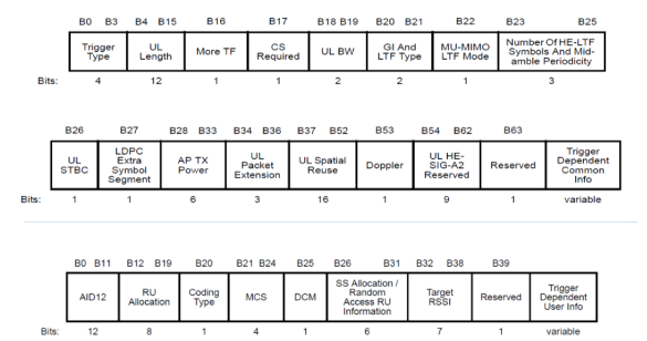
It’s very important to understand what’s a trigger frame? The trigger frame is a new MAC control frame that carries information to identify the station transmitting UL MU PPDU and allocating resources to it. AP has to send the trigger frame in DL MU PPDU to trigger the following UL MU PPDU.

Trigger Frame Format – Common Info and User Info
Trigger frame contains information like RU allocations, MCS, transmit power to use for the transmission of UL MU PPDU. The figure below clearly shows the bit map for each field in the trigger frame.

Trigger Frame Format
Here are some of the important sub-fields:
- RU allocation (B12-B19) says the size and locations of RU allocated to STA.
- MCS (B21-B24) indicates the MCS to be used by STA.
- Target RSSI (B32-B36) indicates the expected RSSI of PPDU on the allocated RU.
Trigger Frame Success and Retransmission
The response in the form of UL TB PPDU (Trigger-based PPDU ) from any of the STAs to a trigger frame implies the successful transmission of a trigger frame. When there is no response from anyone, it is considered to be a trigger frame failure and retransmission is attempted.
Challenges in MU Uplink OFDMA
Since multiple STAs are involved in the UL MU OFDMA transmission, it must be accurate in time, frequency and power when it is transmitted. STAs know their RU allocation, MCS and target RSSI via the trigger frame to do the UL MU transmission. Now all co-scheduled UL PPDU transmission has to arrive in synchronization.

Example of inaccurate time/freq/power
To overcome the challenges, UL MU OFDMA transmission needs the support of transmit power control, timing accuracy, RSSI measurement accuracy etc.
Each STA participating in the UL MU TB PPDU transmission does the power correction with the help of the trigger frame. Trigger frame transmitted by the AP has the AP’s tx power. The STA sets the power considering the path loss if it knows the target power from the trigger frame.
How does the AP allocate resources?
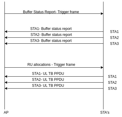
AP allocates the UL resources to STAs to transmit the data. AP needs to know the STAs UL buffer status to allocate the resources efficiently. AP allocates the resources to the STAs which have some data to send. And this is achieved by ‘Buffer Status Report’.
AP asks for a buffer status report via the trigger frame. Each associated STA can send the buffer status report based on the queued UL data. AP may allocate the RU based on the buffer status report received from each STA. As we know, RU allocations, transmit power and MCS to use are conveyed through the trigger frame. AP may receive the UL data from STA in the allocated RUs in response to the trigger frame sent.

Buffer Status
Certainly, Uplink OFMDA is complex but it’s definitely possible. Just like everyone else, excited to know how well it can come out in realtime. Stay tuned to know more about the new features of Wi-Fi 6 and how you can test Wi-Fi 6 features with our SWAT WiCheck 6
